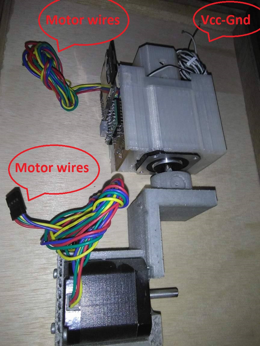
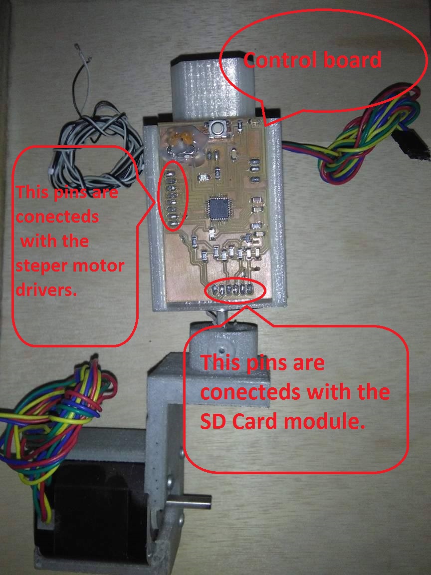
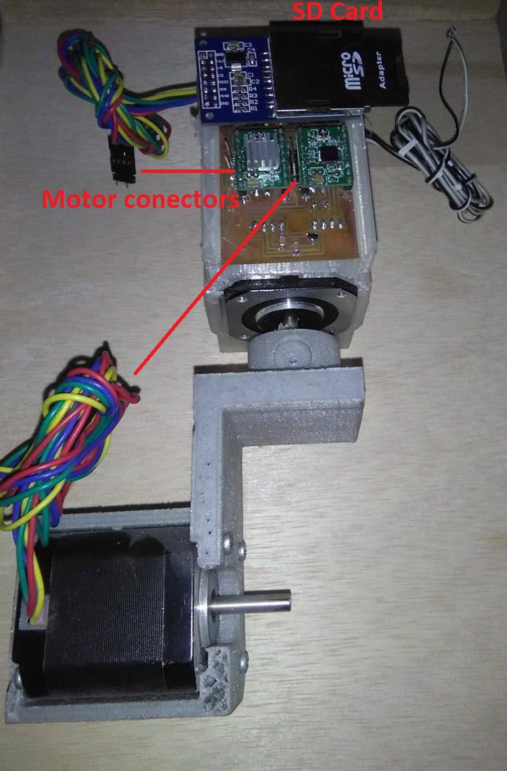
Show how the controller board works together with your system - how is it powered etc. Is there an SD card for each leg/wheel?
How is it powered? What is your input?
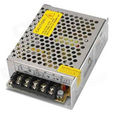
The system is powered with an 12V external voltage source connected with two wires. The anothers wires are of the motor conected drivers.
A input is a external signal or data to be procesed, in my case the imput is the information in the SD Card.
Is there an SD card for each leg/wheel?
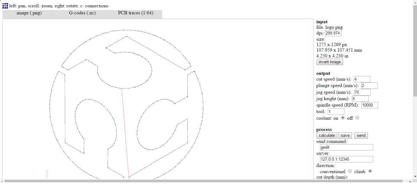
This wheel read a g-code with a SD Card, the g-code have to be created with a computer and exported in a SD Card.
If we want to control more wheels, we need to clone the output signals and conect more wheels like a generic CNC, you can clone a A axis, in this case we could clone to control another wheel more just with one SD Card to controll more wheels.
Did you make 1 wheel to prove your concept - did it prove your concept?
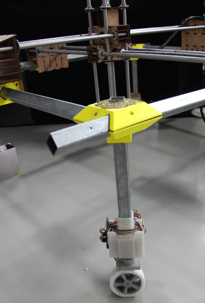
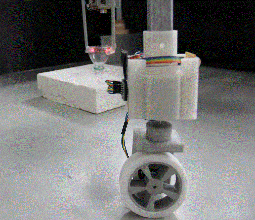
I made a wheel to prove my concept, for this reason and for time, I made just one wheel, but the concept is verifed, because the wheel read the g-code and it transformed to movement to controll the step motors. That is the concept verifed, we could create a g-code and the wheel is going to convert this file in moveement.
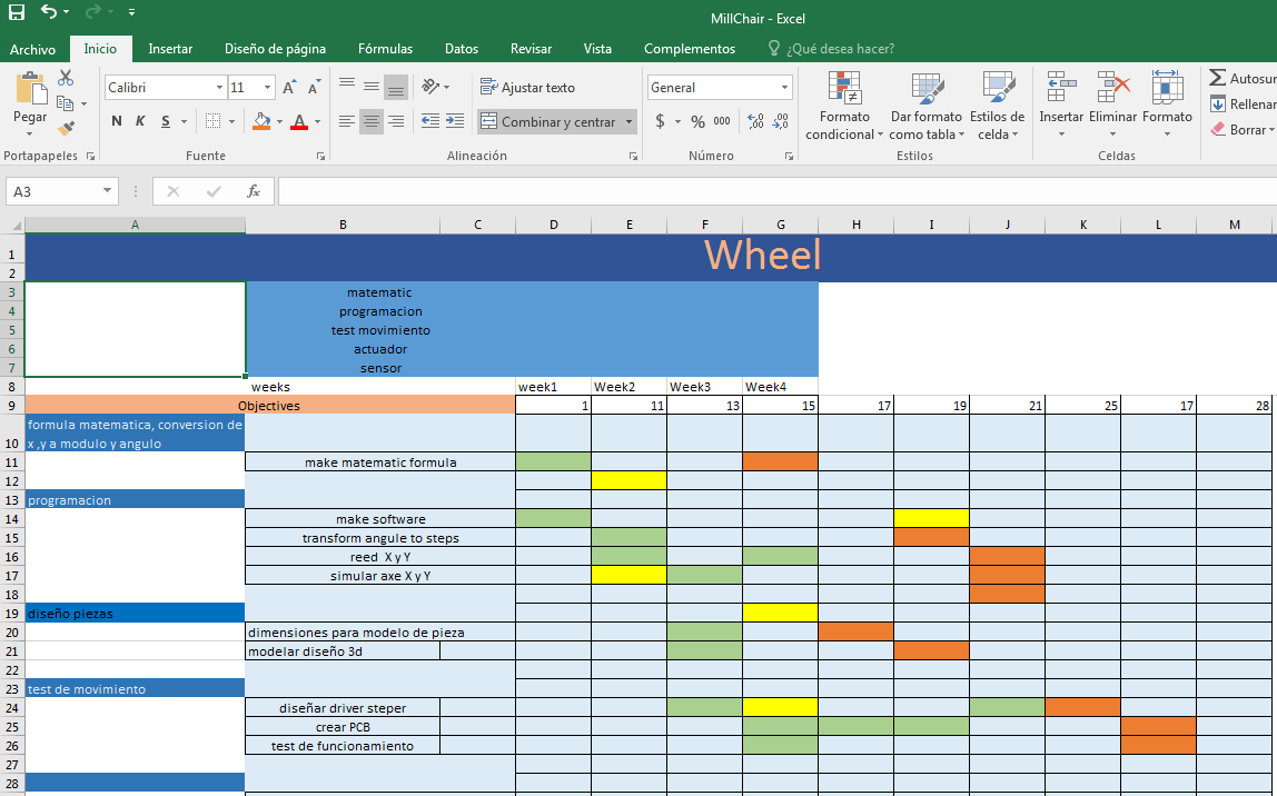
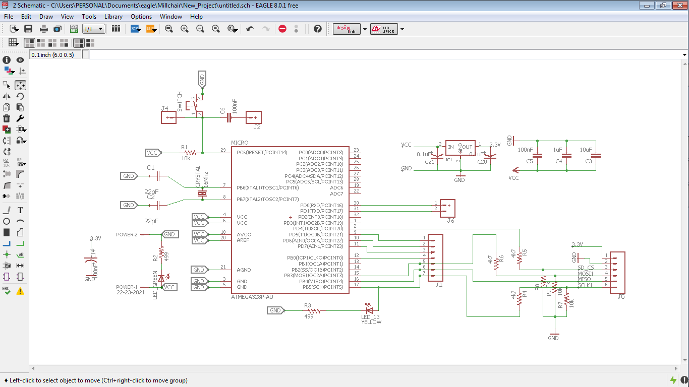
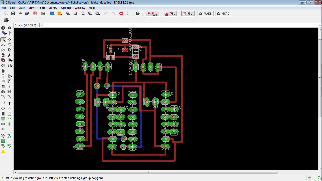
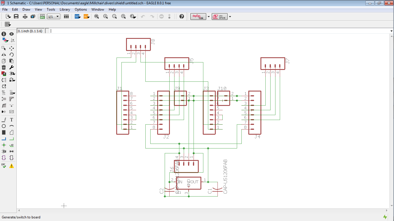
All the connections you can find in the board and schematic files of Eagle PCB , the wires has names to connect. all the files you can download in the final of this page.
Process
I wrote on my personal information, I want to learn more to help people. I want to do an automatic wheelchair,
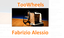
I saw a replica of Toowheels of Fabrizio Alessio from fablab Torino on Fab Lab Yachay and I have a little of experience with automatic wheelchair
The goal is make it move with electric and electronic systems.
Looking for information I found two projects to get information to my project,
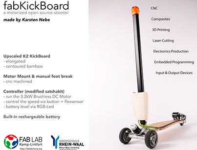
the first project is FabKickBoard - a motorized Kickboard created by Karsten Nebe.
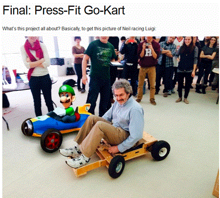
and the second is Press-Fit Go-Kart created by Andrew Mao
.
Idea
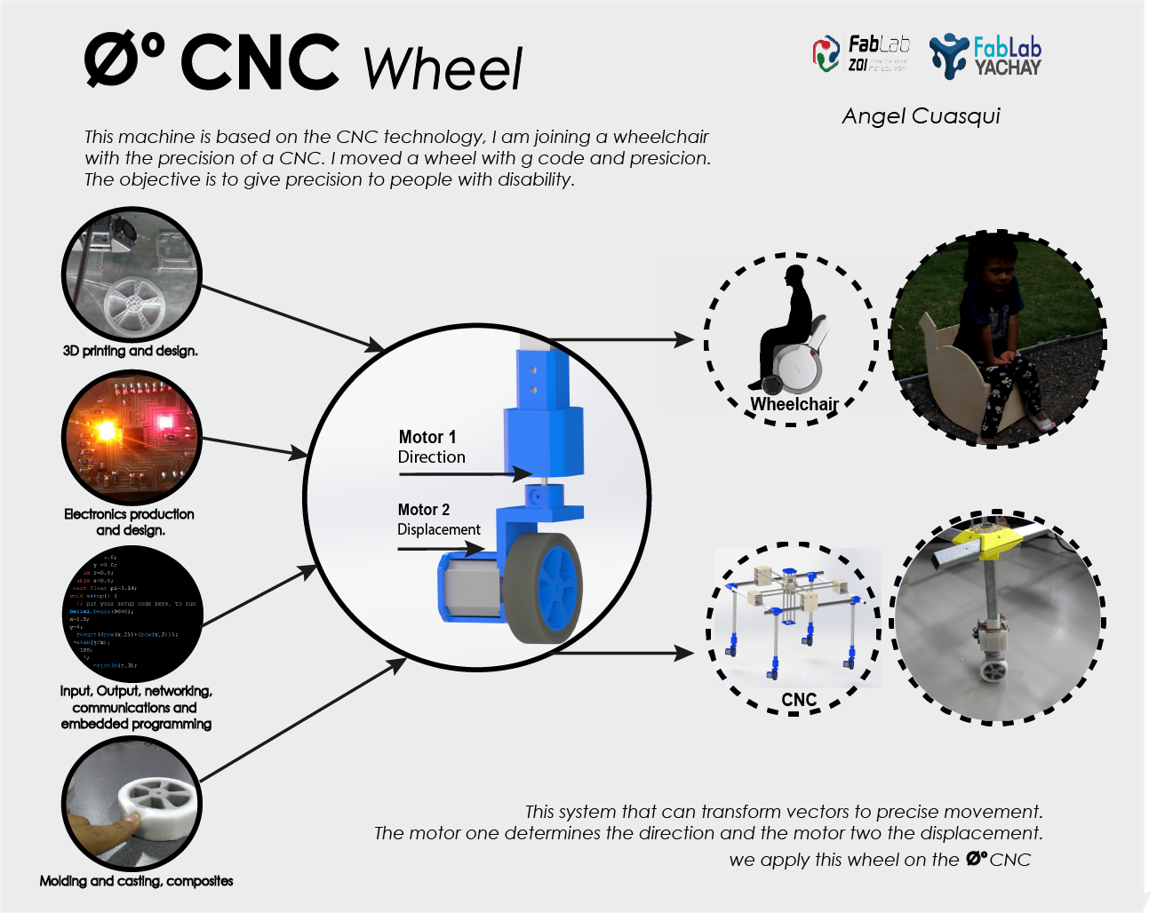
I was talking and thinking about my final project, I started the Fab Academy thinking how to help people, and I am working in my Final project, I decide to call it 0 CNC Wheel, CNC and Wheel it is the idea, we can gives a great possibility to make a lot of things, a wheel with Millimeter displacement, it is all the technology of a CNC on a Wheel. I imagine a people with disability on your CNC Wheel drawing on a tablet or cellphone, he export a gcode, or a file with X Y vectors. and the CNC wheel can make it, that is one of a lot of ideas than I have.
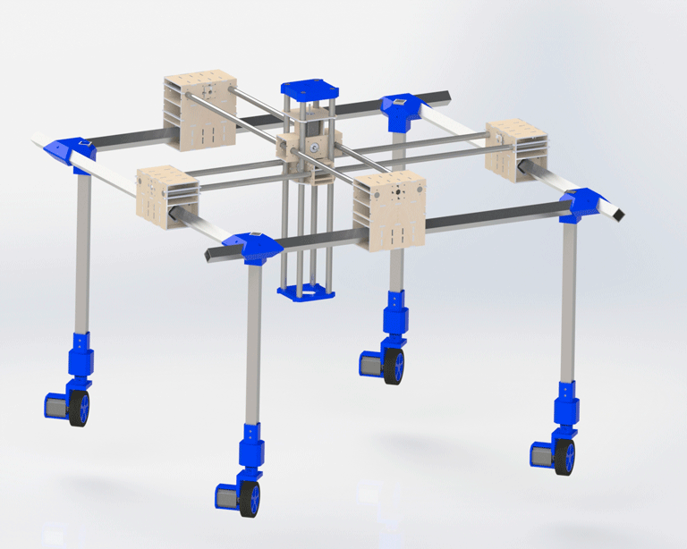
0 CNC Wheel
Work process
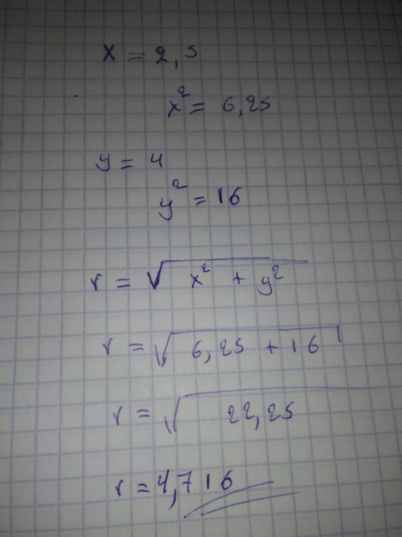
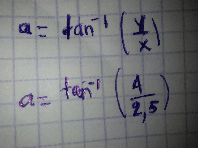
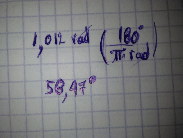
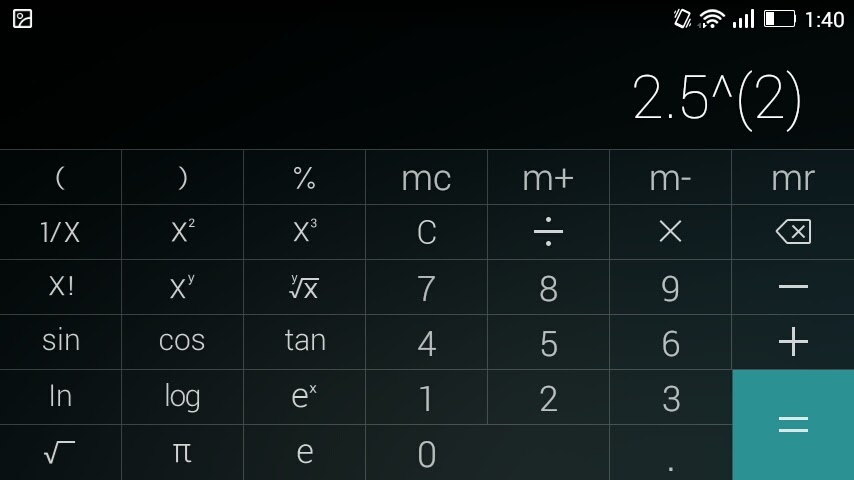
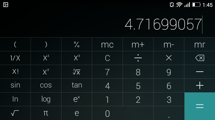
My first step is make a mathematical equation to transform the X, Y and Z axes.I decided to transform this data on angle and module, I used the basic equation of Pythagoras.
The first motor have to give me the direction using the angle and the second motor use the module to give displacement,
That’s the reason to transform the X and Y vectors,
I have the angle to get the direction and the module to get the displacement.
In the next images you can see the equation of Pythagoras with data on x and y. I made it to be sure to make my code.
Embedded programming and SPI Communication
Fabrication and programming of your own fabbed microcontroller PCB, including an input & output device
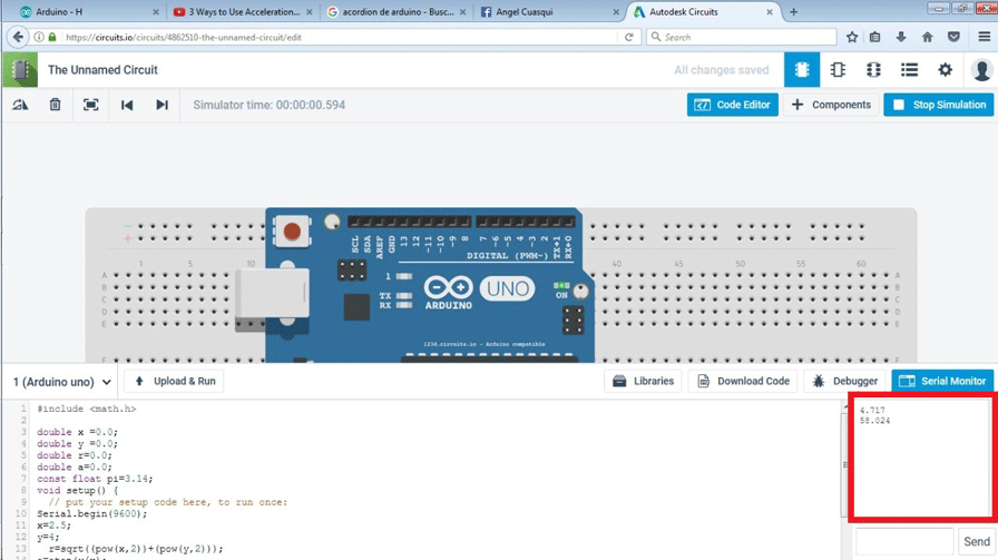
I created the code and simulation on 123D circuit, in the serial port I printed the result, see the red square.
Then I read a file on .txt format.
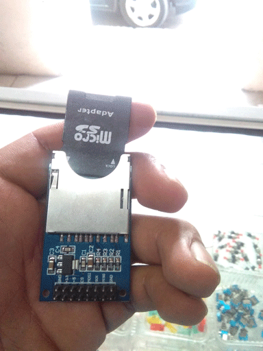
I used a SD Card module to get the information, I connected the module SD with the Arduino, also I created my own version based on satshakit, to replace Arduino
I opened a file and read it line to line, I am learning how to get the data and add the equation of Pythagoras.
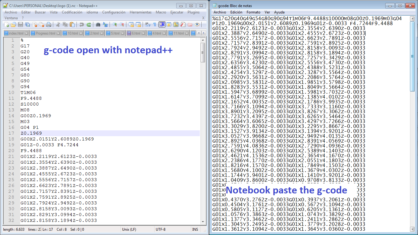
I was working in the code, I need read the file with my code, I generated a file on fabmodules.org to prove mi code.
I opened the file than I generated on fabmodules,
my code just open a .txt file, I have to copy the code on a .txt file.
This .txt file I uploaded to my SD card and
then I put the SD card of my system.
this code read the file, then recognize x and y positions and transform to polar vectors,
I explain what is the reason to make this transformation before,
then I transform the polar vectors to numbers of steps to activate the stepper motors.
I feel so happy because y was proving this code with a different file and when I uploaded the file generated on fabmodules the code run, it was great.
The first lines is cero data. I am going to correct that. now I need to activate the motors with the pololu motors drivers.
In this video you can see the first two numbers are x and y axes , the next two numbers are the polar verctors,
the next is the angle transformed on steps and the module transformed in steps,
the last two numbers is the steps less the previous stesps.
Here is the code than I am using finally. this code read a .txt file and use the axes x,y and z to move my system.
for(int m=0;m {
digitalWrite(steps, HIGH); // This LOW to HIGH change is what creates the
digitalWrite(steps, LOW); // al A4988 de avanzar una vez por cada pulso de energia.
delayMicroseconds(VELOCIDAD); // Regula la velocidad, cuanto mas bajo mas velocidad
delay(20);
}
signed int pd=0;
pd=movi-previo1;
if(pd>0)
{
direccion1=1;
}
else
{
direccion1 = 0;
pd=previo1-movi;
}
previo1=movi;
Serial.println(pd);
//Serial.print(" ");
//Serial.println(previo1);
for(int m=0;m {
digitalWrite(steps1, HIGH); // This LOW to HIGH change is what creates the
digitalWrite(steps1, LOW); // al A4988 de avanzar una vez por cada pulso de energia.
delayMicroseconds(VELOCIDAD); // Regula la velocidad, cuanto mas bajo mas velocidad
delay(20);
}
This code is in the finally of this page to download.
SPI Communication
In the assignment networking and communications,
there you can see the SPI, this is a serial bus of communication, I am using SPI communication to get the information of a file in the SD Card.
I learned more about SPI and SD Card on the forum of Arduino, here the link.
Link to learn about SD Card and SPI Serial bus
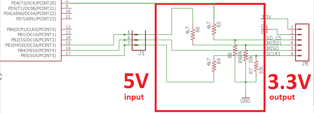
Two important things that you have to know is that the information of Arduino sends on 5V but the SD Card work with 3.3V, for this reason we have to do a voltage divider to get 3.3V.
In the image down you can see the circuit than I made. I used two resistances to get 3.3V the first is 10K and the second is 5.9K ohm.
Also remember connect the input voltage to 3.3V.
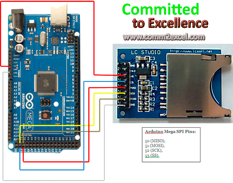
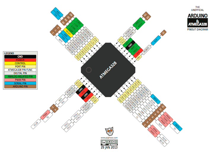
In this picture you can see the pins to connect of Arduino mega, but on my circuit i use atmega328 and I searched the pinout of Atmega328 to know what is the pins to connect.
there is the picture to connection to Arduino mega and the pin out of atmega328
Electronics production and Electronics design
Create your own integrated design
I decided to created a PCB based on satshakit and my needs.
One of my needs is make a voltage divider of 5V to 3.3V, it is because the SD card works with 3.3V. The signals of atmega328 is on 5V but I need to reduce the signals to 3.3V.
also to conect the SD Card I need MISO, MOSI, SCK, and CS.
in tis PCB also I need the pins TX and RX to print in the serial port.
I need four digital pins to control the stepper motors.
and the pins to burn bootloaders
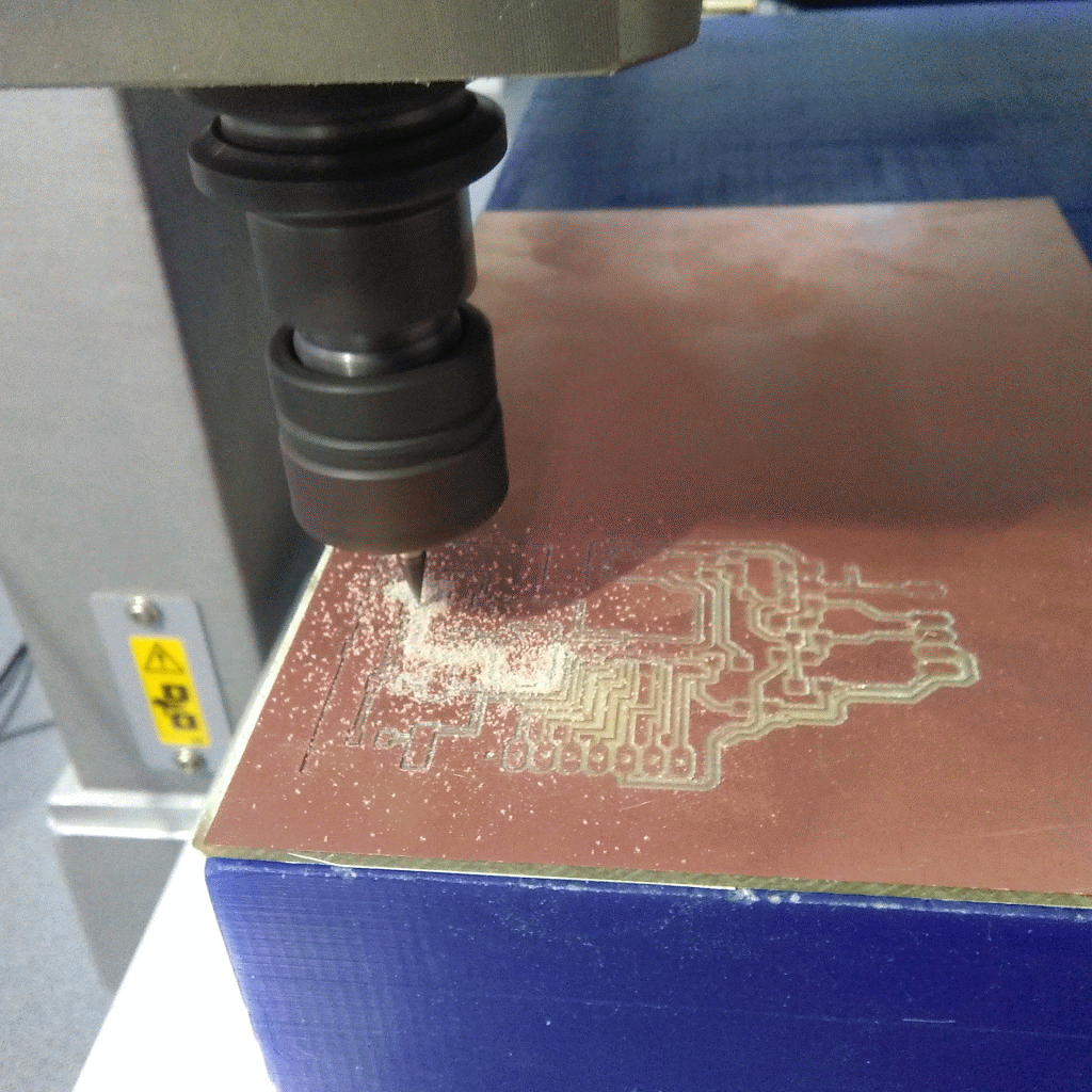
The machine than I am using is Roland MDX-540
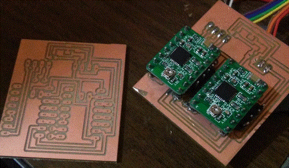
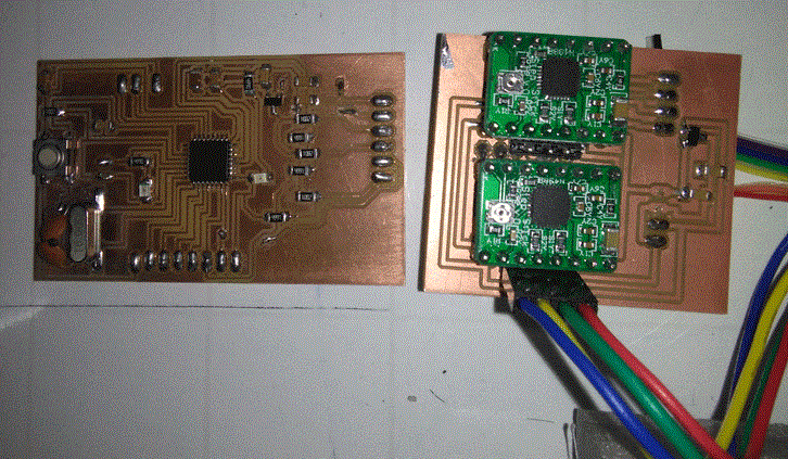
También trabajé en un PCB para reducir el voltaje de 12V a 5V y un tipo de escudo para añadir el controlador de motor paso a paso.
Todos estos archivos fueron creados en eagle PCB y se pueden descargar en la final de esta página.
I was working with a stepper motor driver but I had problems to regulated the current, the Driver is L298N. I am not working with this driver. I am working with A4988 stepper driver.
Here are the two PCB than I designed to my project.
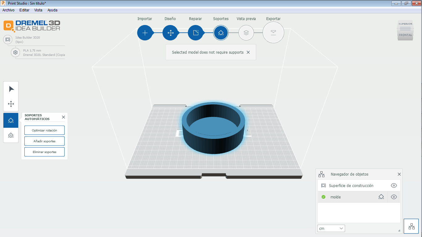
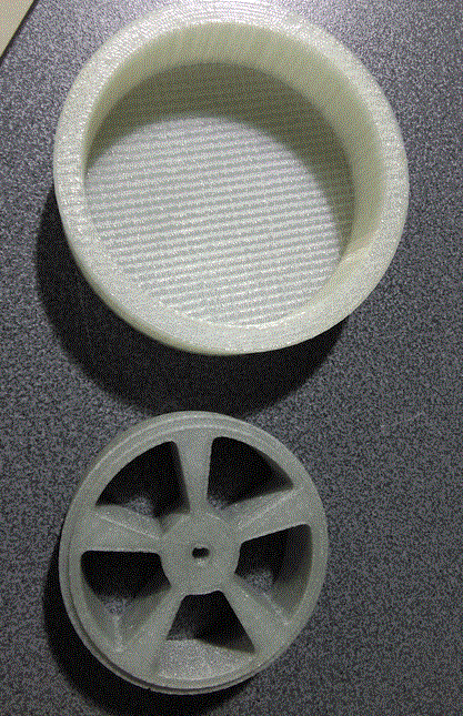
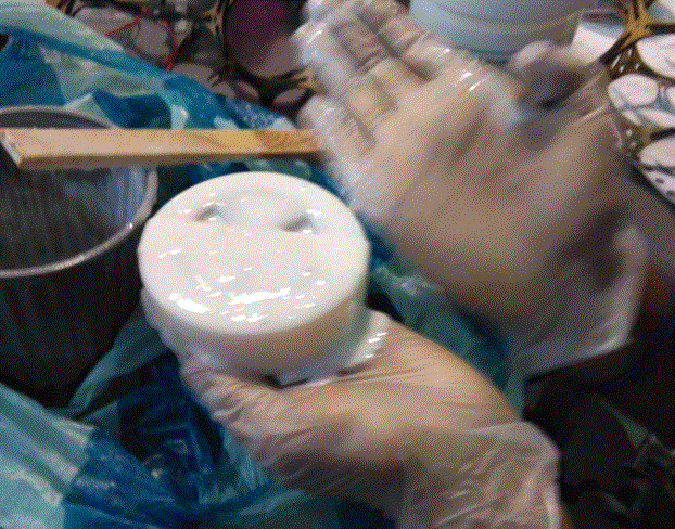
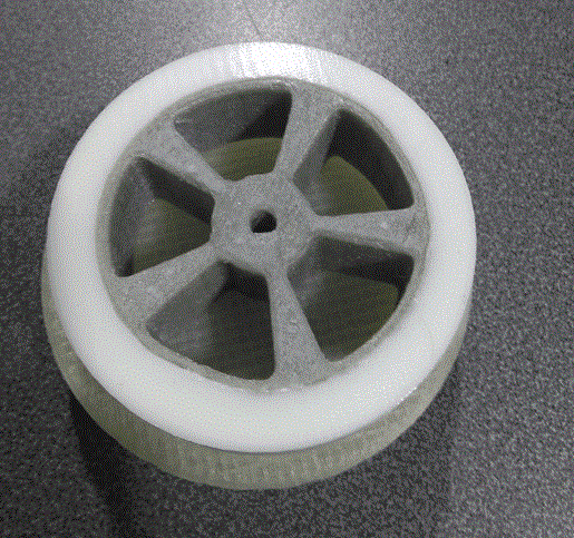
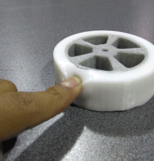
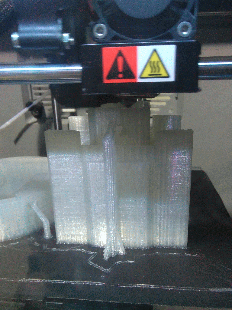
I need wheels to mi CNC Wheel, I designed a mold to my ring, and I used a 3D printer the to get my mold.
The design of this ring is based in the ring of Carlos Andres Moreno Fab Academy 2016, I used the same but I changed the size because my ring is more high.
The 3D printer is a Dremel and the software is Print Studio.
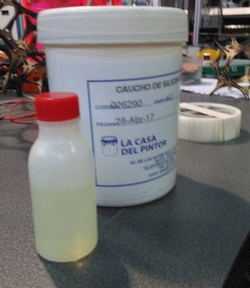
To get the wheel I used a composite, the composite is silicon rubber, if you want to know more about this composition, you can visit my assignments of Molding and casting.
Computer controlled machining
Demonstrate 2D capabilities applied to your own designs
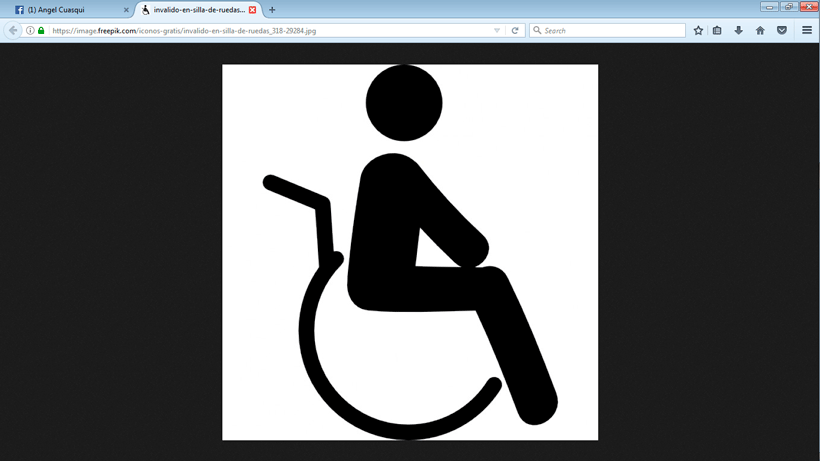
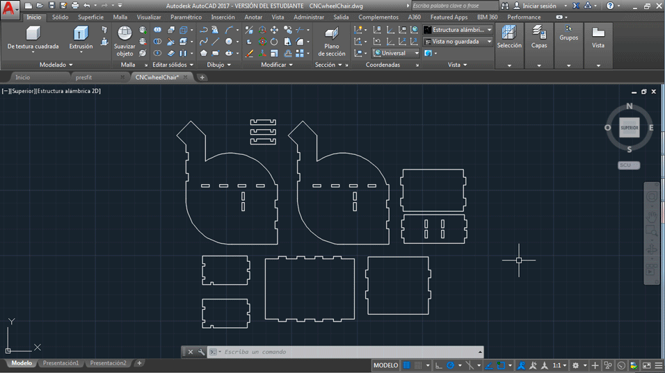
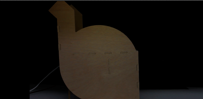
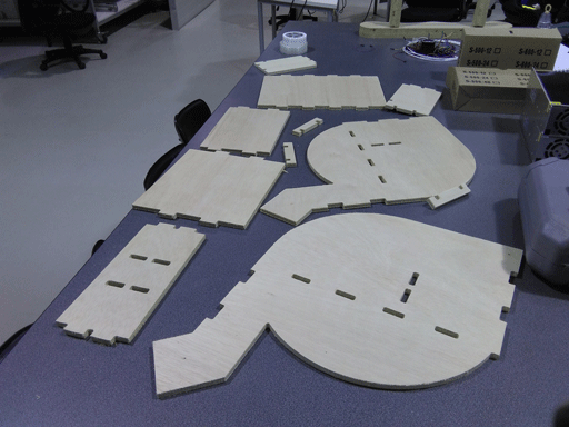
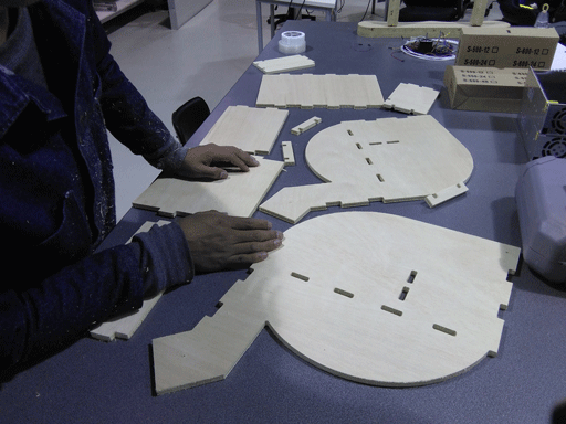
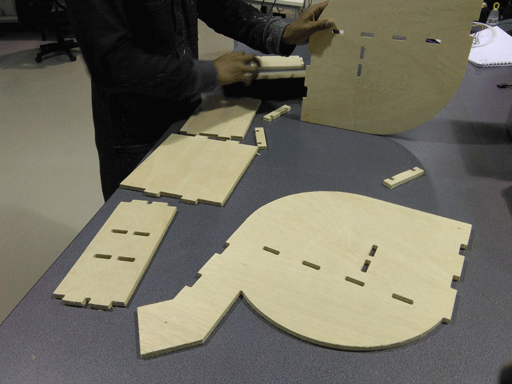
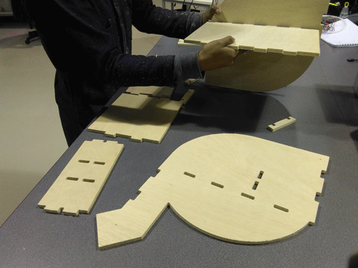
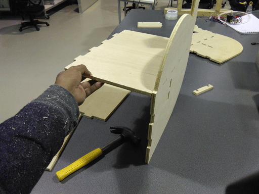
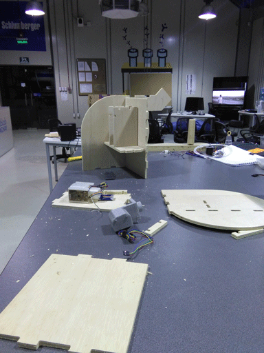
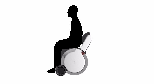
I decide to do a wheelchair, this wheelchair was designed to apply my system. I used AutoCAD to design, the Shopbot machine to do my wheelchair and wood of 9mm. This design is based on the traditional figure of people with disability.
In this process I cut the wood on the shopbot machine I used a milling of 1/4, the wood is on 9 millimeters.
I had to sanding the wood a little to get join the pieces.
I did not use the dog bone feature when cutting the plywood because I was so tired and I forgot it, I had to sand the corners to acople the wood.
3D Design and printing
Demonstrate 3D modelling capabilities applied to your own designs
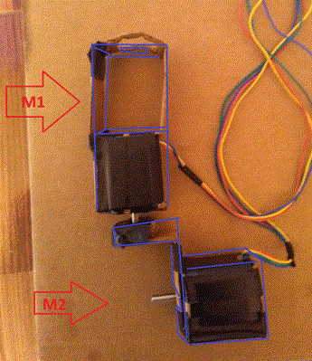
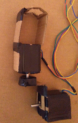
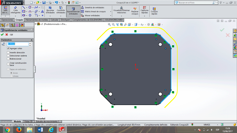
I designed a 3D of the pieces than I needed to do, but the first step was make a model with cardboard to be sure of mi design, see the next pictures.
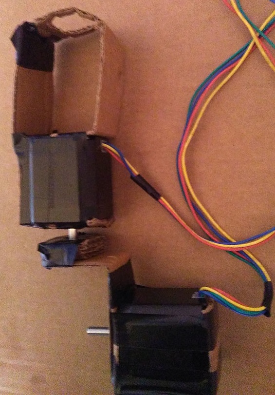
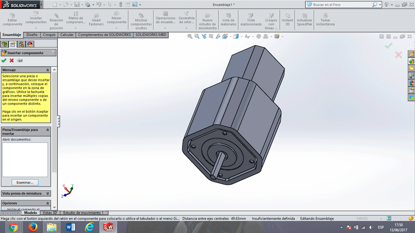
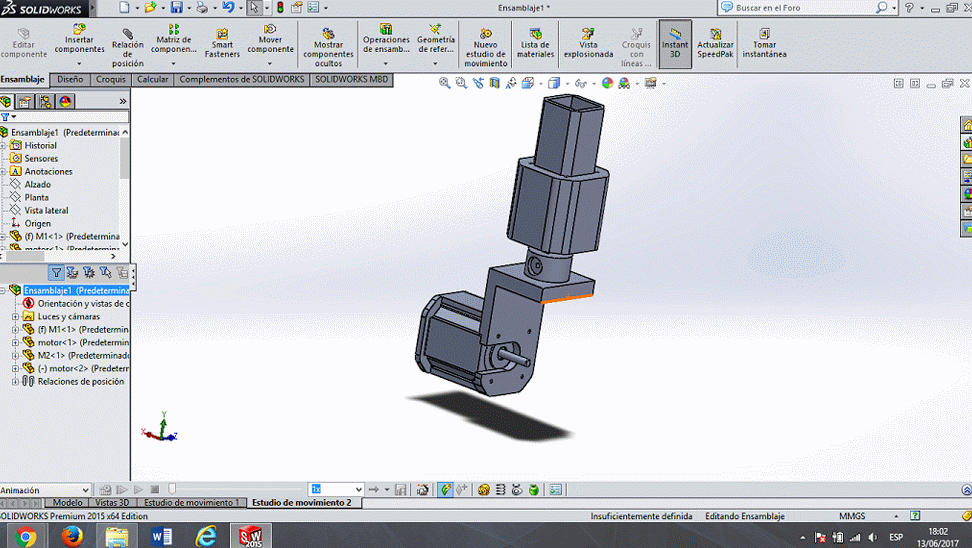
In the pictures you can see two motors the first motor needs to coupling to a fixed base, and the second motor needs to turn 360 degrees.
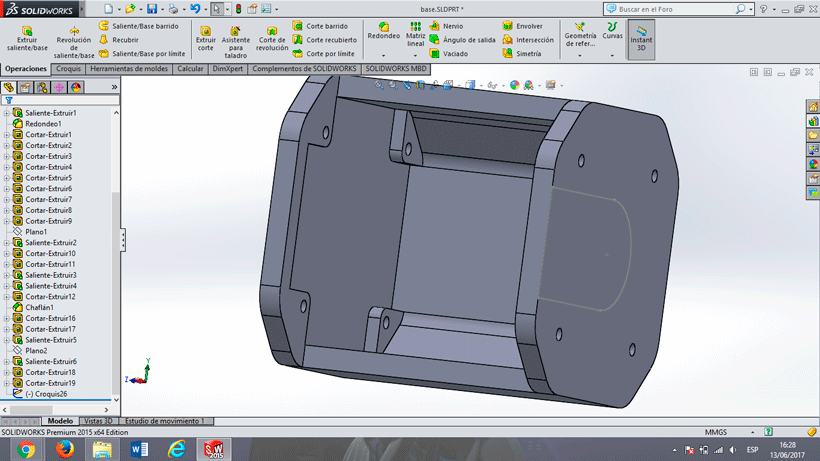
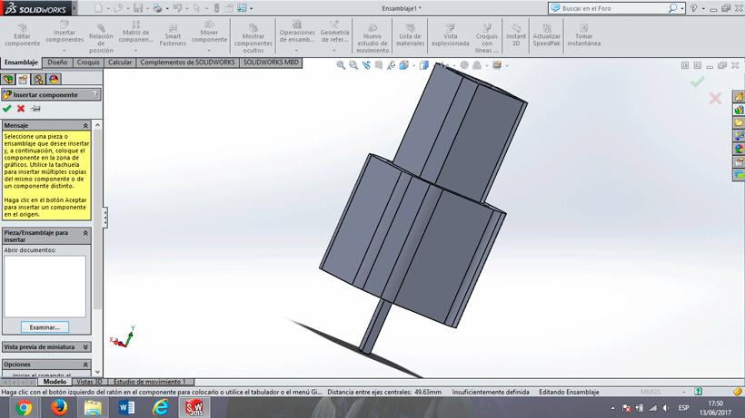
Then this design was created on 3D model to print. I used Solidworks to design the 3D model.
Here you can see the model of the two motors, also I have to say thanks to my coworker Guillermo Guerra because he helped me teaching me a lot of thing of Solidworks.
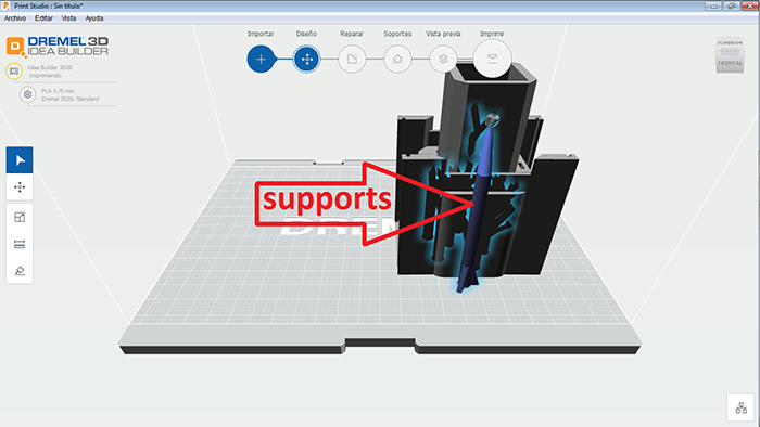
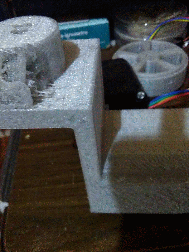
Then I exported this file in .stl format to print. I used the Print Studio software to add the supports necessaries to print. and then i print the file on a Dremel 3D Printer.
Select and apply appropriate additive and subtractive techniques
Questions
What is the need to apply this system on a wheelchair?
Is really important to me follow this project to give precision in this kind of people, in this moment I can upload a file, I could give a way to get forms on the street or make straight lines. I think than I can give a option to work to people with disability to walk.
What has worked? And what hasn't?
The system is working so good, but if you wat to apply this system in different applications you have to take in count capacity of the stepper motors, now it is a prototype, it cannot support weight. Also this system is working with a voltage source it can be changed with a battery.
What did you learn in this process?
I learn 3D design, molding and casting and improve my abilities to design.
0 CNC Wheel System:
This system can be apply in different opinions but I decided to do this project because I was working in an electric wheelchair in the university than I was studying my engineering, I think than the more important in this project to me is the precision, I can know and control the precision in this system, I decided to focus this project on a wheelchair for this reason and because I would like to help in this area, but you can use this system in a different applications, we apply this system on the 0 CNC, you can see the 0 CNC on the assignment of machine design. in the future I want to use this system on a wheelchair, that is my objective.